


As soon as I bought my 360, 1st purchase was a component cable so i could display the HD resolutions on my projector. This made the crappy composite cable supplied with my core pack redundant. I came across guides on the web to convert component cables to vga, but nothing in much depth and nothing for the composite cable.. so here goes.
What you need.
1)A 15 pin VGA socket or cable with one end on. Can chop and use an extension cable.
2)Your original composite cable (3 phono type that came with core 360's)
3)cutters, a knife and a soldering iron
4)multimeter if using a chopped vga cable
part 1 - harvesting the connector.
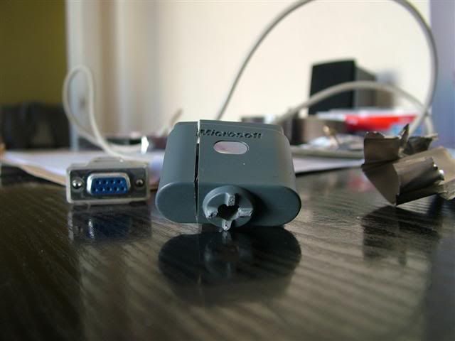
first step is to strip down the 360 connector so chop the cable as close as you can to it.
there is no way into the connector as it is fully moulded with a gel/injected plastic/outer plastic construction so the only way in is to carefully chop this away.
Remove the grey outer sheath with a few slices of your knife and then you are left with the metal carrier and black connector.
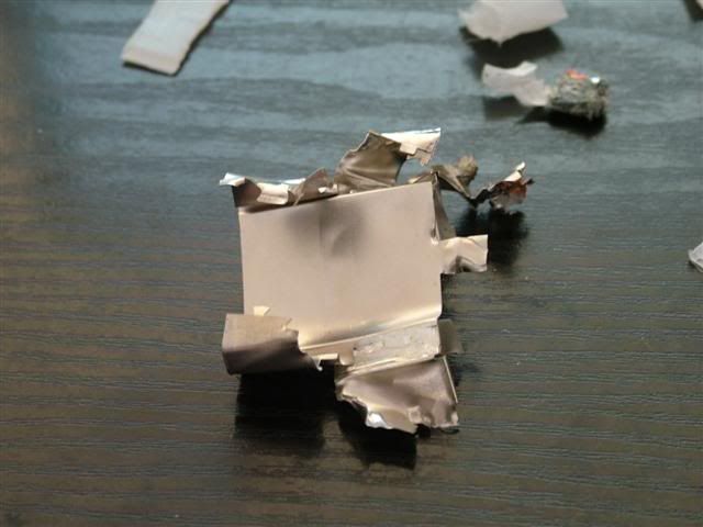
Prise open the metal cover carefully and break it off. It doesnt appear like it will but it comes away fairly easily once you are in. All the metal will be disposed of.
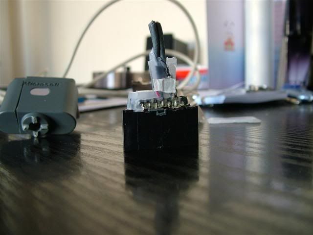
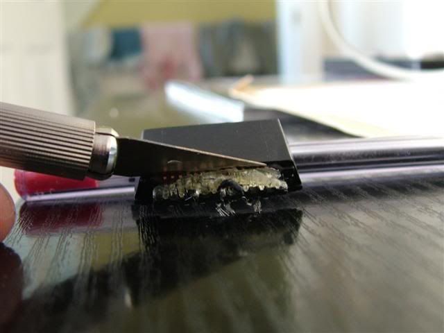
Inside you will come across more soft plastic which will need to be cut and sliced away until you are left with the bare connector. At this stage do not be tempted to pull the front from the back too much as the pins slide in and out and it is easy to pull them too far.
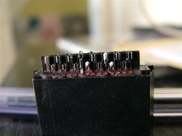
All you are interested in is the black connector and its solder connections, everything else can go !
Next there may be some gel type substance covering some of the pins, so gently pull this off, making sure you are not pulling the pins out of the connector.
Now, warm your soldering iron and clean the remaining bits of wire and any excess solder off the connections.
-----------------
part 2 - preparing your vga lead.
If you have a bare vga plug you can ignore much of this.
Otherwise, use your multimeter on continuity (beep) to identify wires connected to the following pins
pin 1 (red signal)
pin 2 (green signal)
pin 3 (blue signal)
pins 5,6,7,8,10 (ground)
pin 13 (horizontal sync)
pin 14 (vertical sync)
pin 15 (clock)
you can cut the others short and insulate them with some tape.
Strip and tin the wire ends with a little solder.
-----------------
Part 3 - Making the connections.
This is where i hand over to our friend Arakon @ xboxhacker.net who published this diagram, my inspiration
Solder your wires as identified in part 3 as indicated on the diagram.
You dont need to solder all the ground connections as indicated in that diagram. What I did is took all the ground wires that i identified in the previous section wound a few strands of each one together and soldered them to one ground on the xbox connector, specifically the 14th one along on the top row, beacause it was away from all the others.
-------------------
Part 4, Audio.
Go back to your old composite cable and strip the chopped end back, this will expose a metal sheild and inside there, there are 3 seperate cables.
These cables are Red/ground, Black/Ground and White/Ground.
The two you are interested are the red and black wires, you can cut the other short and insulate it.
Strip them back and wind the 2 ground wires together. Tin all 3 ends with a little solder and solder them as per the diagram above. Red is the right channel and black is the left channel. Solder the ground wire to the first pin on the top row in the diagram.
-----------------
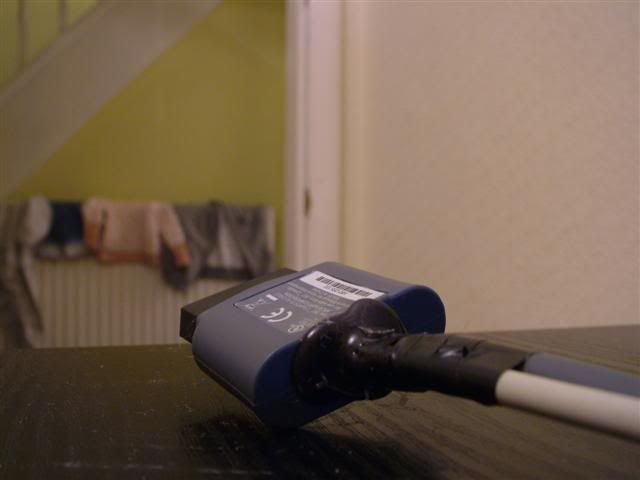
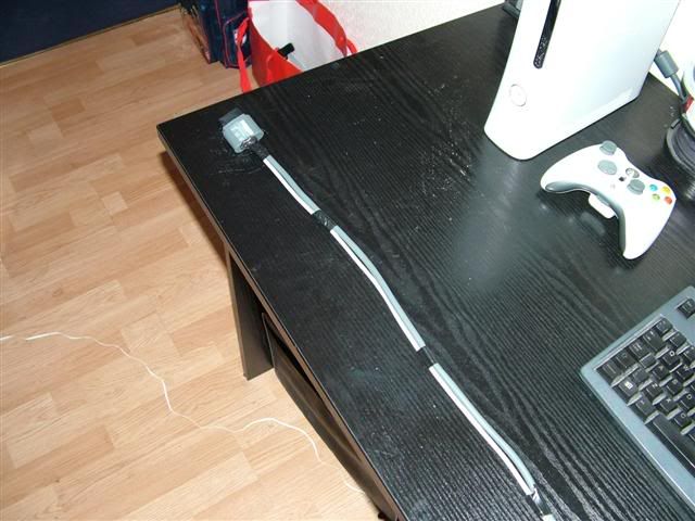
Part 5 - Plugging it in.
Dont make the same mistake i did and not push the connector far enough into the 360, First time i booted up i was greeted by a grainy image full of interference. The connector goes in a fair way and with a fairly definate movement when in properly. Pushed the connector in all the way and was met with a stunningly clear image on my 17" tft.
Into the menus to set the 360 to output 1280x1024 (the panels native res) and its a vision of lovelyness
(ignore the blurring thats my camera being kak !)
---------------------
Part 6 - Still to do...
Look at how the optical output is formed on the HD cable so it can be added here
Make some sort of shell for the cable end so it is protected for insertion/extraction
any questions or comments welcome
cheers,
malty


 Reply With Quote


Social Networking Bookmarks